1.0 OBJECTIVE:
Objective of this report is to provide documented evidence through the verification of installation, operation & performance of Tablet Friability Tester to show that the instrument installed, operated and consistently performed according to predetermine specifications.
2.0 SCOPE :
The scope of this Report is limited to Id No. XYZ
3.0 QUALIFICATION TEAM AND RESPONSIBILITIES:
| DEPARTMENT | NAME & SIGNATURE | RESPONSIBILITY |
| Maintenance | To prepare qualification report. To co-ordinate the entire qualification activity. | |
| Quality Assurance | To execute qualification study in co-ordination with other departments. | |
| Production | To execute qualification study in co-ordination with other departments. | |
| Maintenance | To review the qualification documents. | |
| Head – Quality Assurance | To approve qualification protocol & report. |
4.0 INSTRUMENT DESCRIPTION:
For instrument description, should match as per re qualification protocol
5.0 ACCEPTANCE CRITERIA:
Qualification of the instrument shall be in accordance with the parameters given in Annexures – A, B, C, D, E, F, G, H, I & J of this report.
6.0 OBSERVATIONS:
Qualification shall be executed using following forms:
- Installation verification checklist – Refer Annexure – A.
- Calibration of measuring device– Refer Annexure – B.
- Site inspection checklist – Refer Annexure – C.
- Utility verification checklist – Refer Annexure – D.
- Technical specification checklist – Refer Annexure – E.
- Drum specification checklist – Refer Annexure – F.
- Operation verification checklist – Refer Annexure – G.
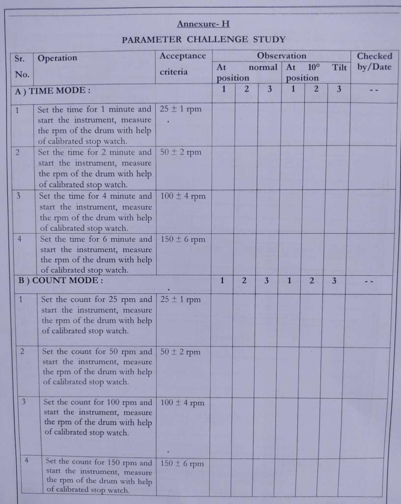
- Parameter challenge study – Refer Annexure – H.
- Power failure challenge study – Refer Annexure – I.
- Performance of instrument – Refer Annexure- J.
Annexure- A
INSTALATION VERIFICATION CHECK LIST
| Sr. No | Checks to be performed | Acceptance criteria | Observation | Checked by/Date |
| 1 | Check for the receipt of the consignment. | It shall be received in good condition. | ||
| 2 | Check for any scratches on the machine body and drums. | It shall not have any scratches on machine body and drums. | ||
| 3 | Check for electrical connection | It shall not observed a loose or damage connection. | ||
| 4 | Check for levelling of the platform. | Air bubble of level indicator should be at centre. | ||
| 5 | Check both drums are properly locked with knob on the shaft. | Both drums should be properly locked with knob on the shaft. |
Annexure- B
CALIBRATION OF MEASURING DEVICES
| Sr. No. | Measuring devices | Acceptance criteria | Observation | Checked by/Date |
| 1 | Vernier Calliper | It should be calibrated within calibration period. | ||
| 2 | Thermometer | It should be calibrated within calibration period. | ||
| 3 | Stopwatch | It should be calibrated within calibration period. | ||
| 4 | Multimeter | It should be calibrated within calibration period. |
Annexure- C
SITE INSPECTION CHECKLIST
| Sr.No. | Parameter | Acceptance criteria | Observation | Checked by/ Date |
| 1 | Room Temperature | 15 to 30°C | ||
| 2 | Room Humidity | 40 to 70 % RH | ||
| 3 | Room environmental checks | – Away from direct sunlight. – Free from vibration. – No corrosive gases. – Free from excess dust and moisture. | ||
| 4 | Table space | Width :15” Length : 18” Height : 20” |
| Sr.No. | Parameter | Acceptance criteria | Observation | Checked by/ Date |
| 5 | Point for electrical connection | Single phase of 230 V AC 50 Hz | ||
| 6 | Base/table level | Levelled sturdy, with no vibration. | ||
| 7 | Earthing | Shall be provided. |
Annexure- D
UTILITY VERIFICATION CHECKLIST
| Sr.No | Parameter | Acceptance criteria | Observation | Checked by/Date |
| 1 | Phase Voltage: | Single Phase, 220/230 VAC, 50/60 Hz. |
Annexure- E
TECHNICAL SPECIFICATION CHECKLIST
| Sr. No. | Test | Acceptance criteria | Observation | Checked by/ Date |
| 1 | Speed | 25 Revolutions per minute (RPM) | ||
| 2 | Speed Accuracy | ± 1 RPM | ||
| 3 | Time range | 01 Sec. to 09 Hrs.59 Min. 59 Sec. | ||
| 4 | Count Range | 01 to 99999 revolutions. | ||
| 5 | Motor | DC Stepper Motor of 3.5 KgCm Torque, 6 Volts | ||
| 6 | Type of the Drum | Electrolab AD Drum and Abrasion Drum. | ||
| 7 | Power Supply | Single Phase, 220/230 V AC, 50/60 Hz | ||
| 8 | Fuse Rating | T 160 mAmp – (For I/P Supply as 220/230 V AC, 50/60 Hz) | ||
| 9 | Dimension | 350mm (L) X 310mm | ||
| 10 | Weight | 12 Kg. (approx.) | ||
| 11 | No. of Drums | 02 Nos. | ||
| 12 | No. of Discharge Trays | 02 Nos. |
Annexure- F
DRUMS SPECIFICATION CHECK LIST
| Sr. No. | Name | Acceptance criteria (As per USP General Chapter – 1216) | Observation | Checked by / Date | ||
| 1 | Drums | – One side removable. | ||||
| — | — | — | Drum 1 and Drum 2 | — | ||
| – | Material | Transparent synthetic polymer with polished internal surfaces. | ||||
| – | Inside Radius of Curved Projection | 80.5 ± 5.0 mm. | ||||
| – | Diameter of Central Hole | 10.0 ± 0.1 mm. | ||||
| – | Diameter of Central Ring | 25.0 ± 0.5 mm. | ||||
| – | Inside Diameter of Drum | 287.0 ± 4.0 mm. | ||||
| – | Outside Diameter of Drum | 302.5 ± 4.0 mm. | ||||
| – | Depth of Drum | 38.0 ± 2.0 mm. | ||||
| – | Tablet Dropping Height | 156.0 ± 2.0 mm. | ||||
| – | – | – | – |
Annexure- G
OPERATIONL VERIFICATION CHECKLIST
| Sr. No. | Operation | Acceptance criteria | Observations | Checked by/ Date |
| 1 | Switch ‘ON’ the power switch. | – The drum shall initialize itself to the loading position. – The display shall now show ‘Start” | ||
| 2 | a) Press ‘TIME’ key to select the “TIME MODE”. | – The MODE indicator LED shall indicate the “TIME MODE”. -The display shall show the previous time values. | ||
| b) Enter the desired value by using numerical keys. Press ‘ENTER’ key to register the value. | The display shall show ‘00’. | |||
| c) Press ‘RUN/HALT’ key. | – The drum shall start rotating in forward direction. – The display shall show elapsed time. – When the test is over the drum shall rotate in reverse direction for discharging the tablets into the tray. – Indication of test over shall show by an audible beep. – The display shall show “END”. | |||
| d) Press ‘RESET’ key. | The instrument shall initialize and will stop at the loading position. | |||
| 3 | a) Press ‘COUNT’ key to select the “COUNT MODE”. | – The MODE indicator LED shall indicate the “COUNT MODE”. – The display shall show the previous count values. | ||
| b) Enter the desired value by using numerical keys. Press ‘ENTER’ key to register the value. | The display shall show ‘00’. | |||
| c) Press ‘RUN/HALT’ key. | – The drum shall start rotating in forward direction. – The display shall show elapsed count. – When the test is over the drum shall rotate in reverse direction for discharging the tablets into the tray. – Indication of test over shall show by an audible beep. – The test over shall show “END”. | |||
| d) Press ‘RESET’ key. | The instrument shall initialize and the will stop at the loading position. |
POWER FAILURE CHALLENGE STUDY (Annexure- I)
| Sr.No | Test procedure | Acceptance criteria | Observation | Checked by/Date |
| 1 | Start the instrument. | Instrument shall run. | ||
| 2 | Turn main power to the instrument OFF. | The instrument shall get OFF. | ||
| 3 | Turn Power ON. | Instrument should not start spontaneously. | ||
| 4 | Start the instrument. | Instrument should resumes from the stop condition with all the parametrs found as before POWER – OFF. |
PERFORMANCE OF INSTRUMENT (Annexure- J)
1.0 Procedure:
Performance of instrument is checked by taking different size or shape of tablets ( different size or shape of tablets causes a regular and irregular tumbling). Initially weighed tablets are transferred gently into the drum from the side slit provided on the drums. The TIME mode is set for 4 minute i.e. 100 rotations. Calculated the friability and result is recorded in following tables.
a) For regular tumbling, set the instrument at normal position, as there is no any irregular tumbling of tablets.
b) For irregular tumbling, set the instrument with 10° tilt with the bench top to prevent any irregular tumbling of tablets.
1.1 Acceptance criteria: Performance of instrument shall be found satisfactory.
1.2 For Normal Position:
Product Name:
Batch No.:
| Sr. No. | Time Set in Minute | Initial weight | Final weight | Friability | Checked by/Date |
| 1 | |||||
| 2 | |||||
| 3 |
1.3 For 10° Tilt Position:
Product Name:
Batch No.:
| Sr. No. | Time Set in Minute | Initial weight | Final weight | Friability | Checked by/Date |
| 1 | |||||
| 2 | |||||
| 3 |
7.0 DEVIATION REPORT:
| Sr. No. | Deviation (s) | Justification for acceptance criteria | Impact on installation, operation and performance |
8.0 CHANGE CONTROL:
9.0 LIST OF ANNEXURE:
10.0 SUMMARY AND CONCLUSION OF QUALIFICATION:
11.0 CERTIFICATION OF QUALIFICATION:
Qualification is satisfactory Yes/No
Hence instrument can be used for routine use. Yes/No
