Pharmaceutical Updates was started to share knowledge among the pharma professionals & it will become helpful to the pharma Professionals. The author of pharmaceutical updates is Chandrasekhar Panda who is having more than 17 years of Experience in Pharmaceutical Quality Assurance department and he has worked in Pharma Companies like Cipla, USV & Aurobindo Pharma Limited.
Vacuum Tray Dryer Installation, Operational and Performance Qualification
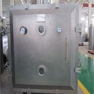
Vacuum Tray Dryer is a static type of dryer used in various industries under vacuum atmosphere to dry temperature sensitive materials as well as pharmaceutical and allied products. It gives complete drying and vaporization of moisture of the product. We at Bhagwati Pharma are manufacturer of Vacuum Tray Dryer. The vacuum tray dryers are been customized according to the clients specification and the available capacities ranges from 6 to 96 trays per batch.
They are suitable for various purposes that includes pharmaceutical, Herbal, chemical & foodstuff.
Vacuum Tray Dryer works on the principle of conduction considering the vacuum conditions. There are several shelves placed under which products are placed. Top shelves gives proper heating and helps to prevent dried powder from escaping into the solvent extraction system. Baffles are been placed between the shelves. It contains an inlet and outlet nozzle both are connected to its own header throughout its own nozzle.
Equipment Name :
Vacuum Tray Dryer
Equipment Model No.:
MEVTD 96 G
Equipment Sr. No.:
858
Equipment ID No.:
XYZ
Equipment Area :
Drying room
Equipment Manufacturer Name :
Millennium Equipments Private Limited.
Equipment Application :
For drying of wet granules and pellets
Report Date :
REPORT APPROVAL:
Prepared by
Checked by
Checked by
Checked by
Approved by
Signature
Date
Name
Department
Production
Quality Assurance
Production
Head -Maintenance
Head – Quality Assurance
OBJECTIVE:
To record the findings of installation, operational and performance qualification of vacuum tray dryer having ID. No. XYZ.
2.0 SCOPE:
The scope of this report is limited to vacuum tray dryer having ID. No. XYZ.
RESPONSIBILITIES:
Maintenance Officer/Executive:To prepare qualification report and co-ordinate the entire qualification activity.
Quality Assurance Officer/Executive: To witness the qualification study and ascertain that the study is conducted as per the protocol.
Production Officer/Executive: To execute qualification study in co-ordination with other departments.
Head Maintenance: To review the qualification documents.
Head Quality Assurance: To review and approve the qualification documents.
EQUIPMENT DESCRIPTION:
Refer installation qualification protocol.
PROCEDURE:
Qualification of the equipment should meet the acceptance criteria outlined in the following steps.
Installation Verification Report
Sr. No.
Check point
Acceptance Criteria (Specification)
Observations
Checked by Sign/Date
1
Visual inspection of the equipment.
Visually there should not be any abnormality.
2
Check the area of installation (Dryer area cubicle).
Area of installation should have sufficient space for operation and servicing of the equipment.
3
Check the levelling of the machine using level indicator.
Air bubble shall be at centre position of level indicator.
4
Check the major components and their electrical cables for housing and anchoring.
Major components and their electrical cables shall be securely housed and anchored.
5
Check the electrical ports.
All electrical ports shall be cleaned.
6
Check the electrical circuit diagram.
All electrical connections shall be found connected as per electrical circuit drawing (reference No. DW-CE010)
Technical Specification Verification Report
Sr. No.
Check point
Acceptance Criteria (Specification)
Observations
Checked by Sign/Date
1
Loading capacity
96 trays with approx 2 – 3 kg material in each trays
2
Dimension
Approximate 2750 (L) x 1900 x 2400 (H) mm
3
Heating shelfs
Heating shelf’s shall be provided for holding and heating the trays.Sufficient distance shall be provided between two trays after mounting the trays on the shelfs.
4
Door bolts
Door bolts shall be provided to lock the vacuum chamber door.
5
Vacuum pump
Vacuum pump facility shall be provided to generate the vacuum in the chamber.
6
Condenser
Condenser facility shall be provided for condensing the vapors drawn from vacuum chamber.
7
Receiver
Receiver shall be provided to collect the condensate solvent and to draw vapour through vacuum pump.
8
Digital temperature indicator cum controller
Digital temperature indicator cum controller shall be provided to control the incoming hot water temperature.
9
Digital temperature indicator
Digital temperature indicator shall be provided to display the inlet temperature and product temperature of dryer.
10
Circulation pump
Circulation pump shall be provided to circulate the hot water through drying equipment and tank.
11
Vacuum break valve
Vacuum break valve shall be provided in front of equipment for easy access.
12
Nitrogen purging valve
Nitrogen purging valve shall be provided in front of equipment for easy access.
13
View glass
View glass shall be provided in front of equipment to view the indoor material.
14.0
Driving/electrical parts
14.1
Driving and electrical parts
Driving and electrical parts shall be covered with SS304 material. There shall be separate cabinet for electrical parts to avoid pollution from driving parts.
15.0
Operating panel
15.1
Operating panel
Operating panel shall be installed in front of equipment for easy access.
15.2
Emergency stop button
Emergency stop button shall be provided on operating panel to stop the equipment in emergency.
Sub Components Specification Verification Report
Sr. No.
Check point
Acceptance Criteria (Specification)
Observations
Checked by Sign/Date
1
Condenser
Qty.: 1 No.
2
Receiver
Qty.: 1 No.
3
Vacuum pump
Qty.: 1 Set.
4
Circulation pump
Qty.: 1 Set.
5
Motor
Qty.: 1 No.
6.0
Sensor details
Incoming hot water temperature sensor
Qty.: 1 No.
Inlet temperature sensor
Qty.: 1 No.
Product temperature sensor
Qty.: 1 No.
7.0
Electrical parts
Rupture disc/ Explosion vent
Qty.: 1 No.
8.0
Pneumatic parts
Inlet control solenoid valve
Qty.: 1 Set
Steam inlet control valve
Qty.: 1 Set
Vacuum gauge
Qty.: 1 Set
Measuring Device Calibration Verification Report
Sr. No.
Measuring Device
Acceptance Criteria
ID. No./Sr. No.
Calibration Done On &Calibration Due Date
Observation
Checked by Sign/Date
Multimeter
It shall be within its calibration period.
Utility Verification Report
Sr. No.
Utility parameter
Acceptance Criteria (Specification)
Observations
Checked by Sign/Date
Electrical
Three phase 415 V AC ± 10% and 50 Hz ± 5%.
Steam supply
NLT 6.0 kg/cm2
Safety Features Verification Report
Sr. No.
Safety features
Acceptance Criteria (Specification)
Observations
Checked by Sign/Date
1
Edges
Edges of construction shall be rounded.
2
Electricity
The equipment shall be earthed.
3
Driving part
Driving part shall be covered.
4
Emergency stop button
Emergency stop switch shall be provided.
5
Sealing system
The equipment shall consist of inflatable gaskets.
6
Vacuum relief plate/explosion disk
Rupture disc provision shall be provided to opens at a pressure of 0.25 bar.
7
Control panel
Control panel shall be flameproof.
Material of Construction (MOC) Verification Report
Sr. No.
Component
Acceptance Criteria (Specification) for MOC
Observations
Checked by Sign/Date
1
Chamber
SS 316
2
Tray
SS 316
3
Heating shelfs
SS 316
4
Condenser
SS 316
5
Receiver
SS 316
6
Support columns/legs
SS 304
7
Hot water distribution headers
SS 304
8
Tank
SS 304
9
Steam inlet control valve
SS 304
10
Silicone rubber gaskets
Food grade
Test/Inspection Certificate Verification Report
Sr. No.
Check point
Acceptance Criteria (Specification)
Observations
Checked by Sign/Date
1
Motor
It shall be tested/inspected for its performance.
2
Vacuum pump
It shall be tested/inspected for its performance.
3
Circulation pump
It shall be tested/inspected for its performance.
4
Sensor
It shall be tested/inspected for its performance.
5
Vacuum gauge
It shall be tested/inspected for its performance.
6
Control panel flame proof
It shall be tested/inspected for its performance.
7
Rupture disc
It shall be tested/inspected for its performance.
8
Steam inlet control valve
It shall be tested/inspected for its performance.
9
Wall panel insulation material
It shall be tested/inspected for its performance.
10
Vacuum tray dryer
Guarantee/Warrantee certificate shall be provided.
Note: Whether component is tested /inspected of its performance shall be verified based on the test/inspection certificate provided by the manufacturer.
Operational Functionality Verification Report
Sr. No.
Operation
Acceptance Criteria
Observations
Checked by Sign/Date
1
Turn the main switch panel (red) ON/OFF button to ON position.
Main panel shall turn ON.
2
Turn the main switch panel (red) ON/OFF button to OFF position.
Main panel shall turn OFF.
3
Press (green) ON button of hot water pump
Hot water pump shall turn ON.
4
Press (red) OFF button of hot water pump
Hot water pump shall turn OFF.
5
Press (green) ON button of vacuum pump
Vacuum pump shall turn ON.
6
Press (red) OFF button of hot water pump
Vacuum pump shall turn OFF.
7
By pressing temp set (green) button set the hot water temperature at 90°C.
Hot water temperature shall be entered successfully.
8
By pressing up (green) button increase the set hot water temperature.
Set hot water temperature shall increase successfully.
9
By pressing down (green) button decrease the set hot water temperature.
Set hot water temperature shall decrease successfully.
Temperature Verification Report
Sr. No.
Operation
Acceptance Criteria
Observations
Checked by Sign/Date
1
Set the hot water system temperature at 40°C and record the hot water inlet temperature and product temperature from temperature controller panel.
For information only
2
Set the hot water system temperature at 50°C and record the hot water inlet temperature and product temperature from temperature controller panel.
For information only
3
Set the hot water system temperature at 60°C and record the hot water inlet temperature and product temperature from temperature controller panel.
For information only
4
Set the hot water system temperature at 70°C and record the hot water inlet temperature and product temperature from temperature controller panel.
For information only
5
Set the hot water system temperature at 80°C and record the hot water inlet temperature and product temperature from temperature controller panel.
For information only
6
Set the hot water system temperature at 90°C and record the hot water inlet temperature and product temperature from temperature controller panel.
For information only
Performance Verification Report LOD Report:
Minimum capacity of VTD:
Product Name :
Batch No.:
Batch Size :
Sr. No.
Sample Location
LOD Result at Initial
LOD Result at End
Checked by sign/date
1
Top Centre Tray
2
Middle Centre Tray
3
Bottom Centre Tray
LOD Report:
Maximum capacity of VTD:
Product Name :
Batch No.:
Batch Size :
Sr. No.
Sample Location
LOD Result at Initial
LOD Result at End
Checked by sign/date
Top Centre Tray
Middle Centre Tray
Bottom Centre Tray
Temperature mapping study report:
Temperature mapping study is carried out with maximum batch size (i.e. by loading 96 trays with approximately 2 to 3 kg material in each tray) with data recording interval of 15 min.
Product Name :
Batch No.:
Batch Size :
Minimum temperature location:
Highest fluctuation location:
Maximum temperature location:
DEVIATION REPORT:
Sr.No.
Deviation (s)
Justification for acceptance criteria
Impact on installation, operation and performance
CHANGE CONTROL:
LIST OF ANNEX:
SUMMARY AND CONCLUSION OF QUALIFICATION:
CERTIFICATION OF QUALIFICATION:
Qualification is satisfactory. Yes/No
Hence equipment can be used for routine use. Yes/No